Structure and selection of power of 3-phase transformer | Galaxy M&E
3-phase transformers have many different structures based on their functions and cooling methods. In this article, Galaxy Electrical and Mechanical will provide information related to the. classification, structure and how to choose the power of 3-phase transformers to meet the load demand.
1. Classification of 3-phase transformers
1.1. Based on the function of the transformer:
- Transmission transformers: With an output voltage of 35 kV or higher are mainly used for electricity transmission to the national grid.
- Distribution transformers: Having an output voltage of less than 35 kV. Distribution transformers are mainly used for the downstream, application for residential areas, industrial zones, offices, industrial production facilities or public places, state agencies ...
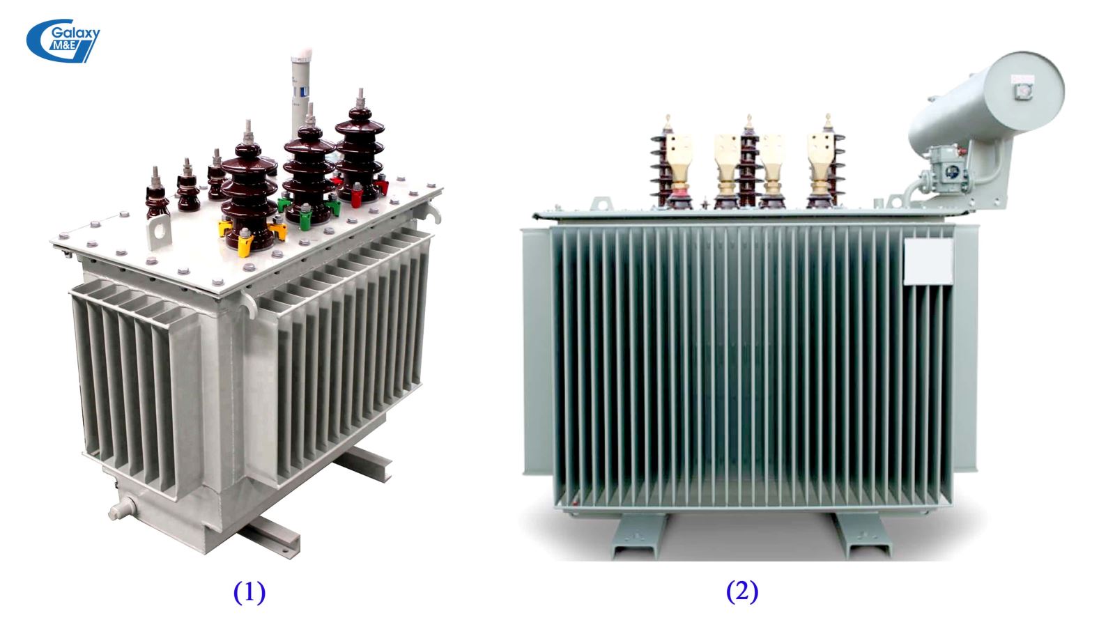
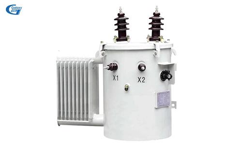
Closed transformers (1) and open transformers (2).
1.2. Based on the type of cooling:
- Closed transformer: A phrase that refers to an oil-cooled transformer, radiators rely on heat sink and there is no extra oil tank installed on the lid.
- Open transformer: A phrase indicating transformer with an auxiliary oil tank that supports the circulation and convection of cooling oil in the barrel.
- Dry transformers: Cool with natural air or forced cooling.
- SF6 air-cooled transformer: This is the most advanced cooling technology today. This type of transformer is also known as GIS transformer.
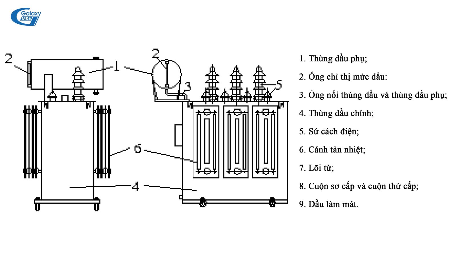
Design of a 3-phase transformer (open type).
2. Structure of a 3-phase transformer
In terms of structure, 3-phase transformers have a similar structure to 1-phase transformers, but due to the use of 3-phase voltage (input) and 3-phase power supply, the structure will be more complicated. 3-phase transformer have 3 main parts: Magnetic core, coil, housing.
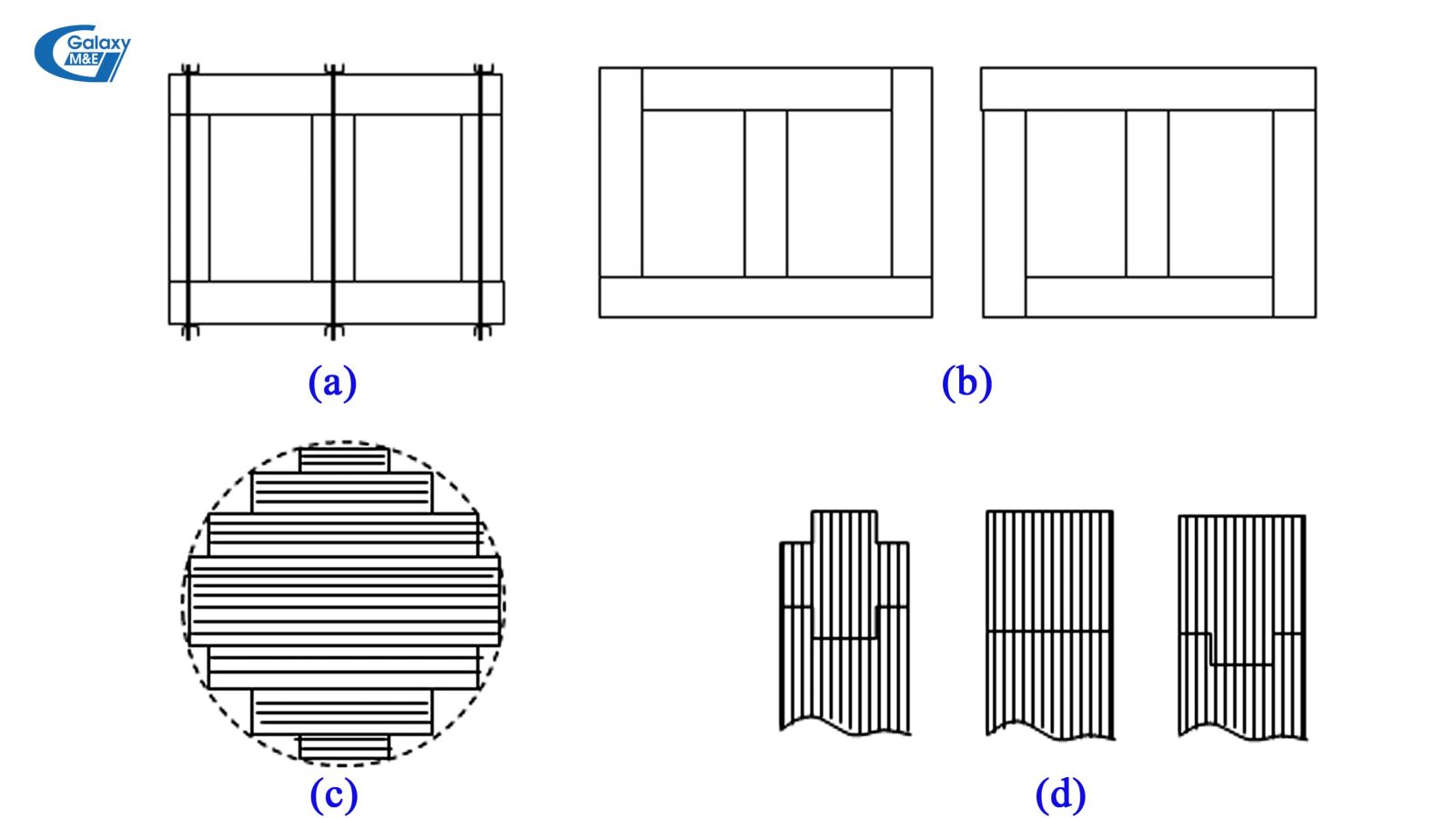
Structure of a magnetic core of a transformer.
2.1. Steel core (magnetic core) of the machine
In terms of shape, the magnetic core of a 3-phase transformer has 3 types: round, oval, rectangular cores. The magnetic core is assembled by corrugated iron sheets with a thickness of from 0.23 mm to 0.3 mm. The core’s material is usually silicon steel with low iron loss from 0.8 to 0.9 W / kg. The steel cores are coated with surface insulation to reduce the loss due to eddy currents.
Steel core consists of 2 parts: Head and gong
- Head (T): The upper part has wrapping.
- Gong (G): Connects the pillars together into a closed magnetic circuit, on which there is no wrapping.
- Head and bolt can be assembled separately, then tightened with screws and bolts (a);
- Pillars can also be alternately joined: Steel sheets for making pillars are assembled simultaneously and alternately in sequence a, b (b);
- Cross section of steel pillars are usually made up of nearly circular steps (c);
- The horizontal section of the ridge makes it simpler: A square, a cross or a T (d).
2.2. Wrapping of 3-phase transformers
Coils in transformers are divided into two types, low voltage and high voltage.
Low-voltage coil characteristics:
- Wrapping coils for small machines up to 100 kVA;
- Foil wrapping coils for transformers greater than 100 kVA;
- Helical wrapping;
- Galet coils for intermediate transformers.
High voltage coil characteristics:
- Multi-layer wrapping coils;
- Galet coil.
General characteristics of high and low voltage wrapping:
- The coils are arranged in a concentric fashion;
- In order of corrugated iron core - low voltage coil - high voltage coil - adjustable coil.
- The coils have the same height, and the loops are arranged along the height. This arrangement reduces additional losses as well as short-circuit forces between the coils.
Insulation of coils:
When wrapping, all the wire loops in the coil are insulated with insulating paper. Most of the DDP (Diamond dot paper) insulation paper from Germany is used on transformers. Between the coils, and the corrugated iron core is also an insulating cover (Pressboard).
2.3. Wire terminal block
- How to connect three-phase AC wrapping is classified as follows: Triangular connection (D, d); Matching stars (Y, y); Zigzag connection (Z, z); Open connection (III, iii).
- Commonly used winding connections:
* Yyn0 or Yzn: Used for distribution transformers;
* YNyn0: Used for transformers having neutral points with long-term load and rated current;
* YNd: Used for transformers connected to generators and main transformers in power plants and large transformer stations.
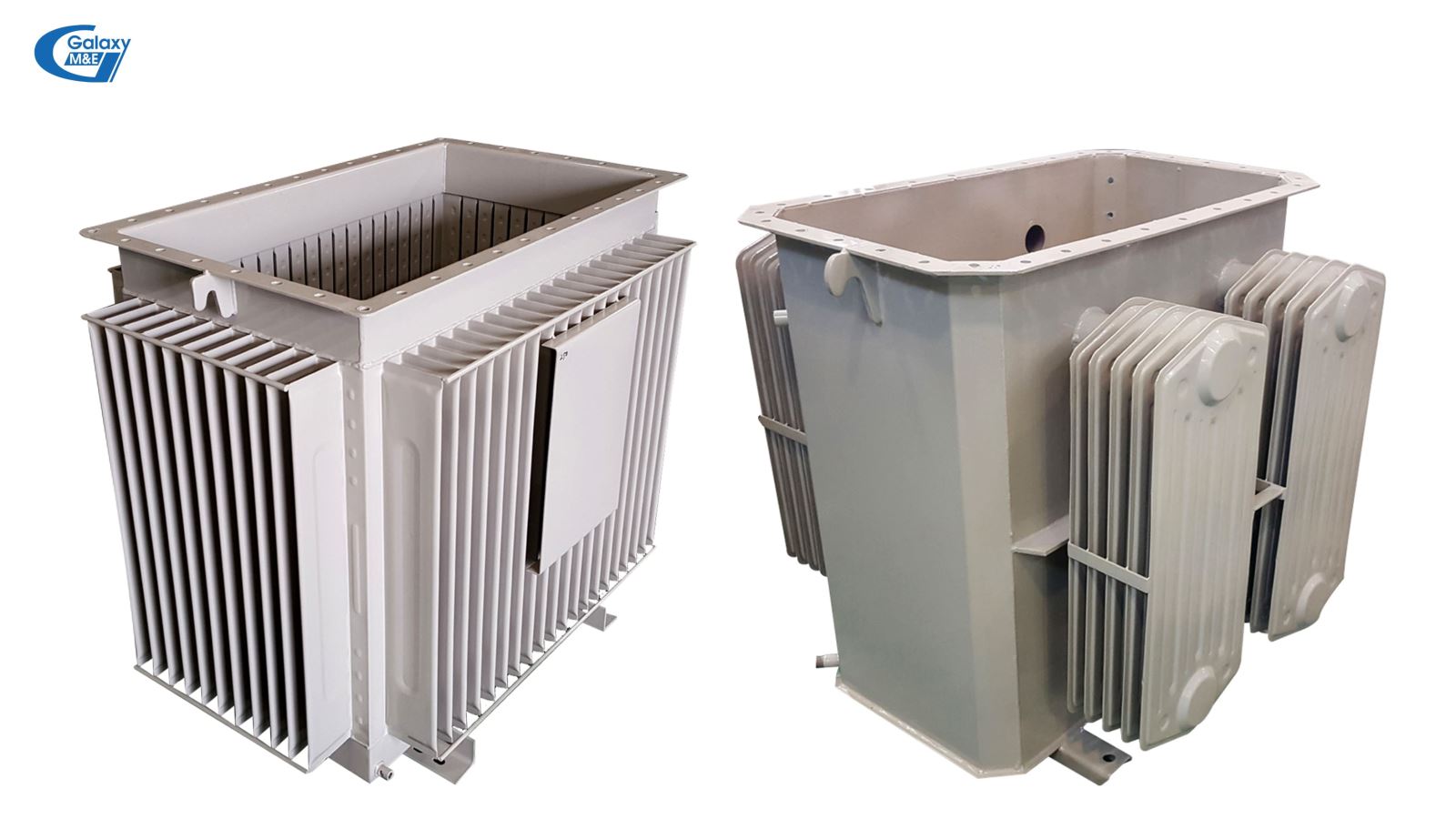
3-phase transformer tank.
2.4. 3-phase transformer chassis
3-phase transformer housing are divided into 2 parts: The case and the lid.
3-phase transformer tank.
Tank: The tank is made of steel, the shape and structure of the box depends on the capacity of the machine. When the transformer is working, some of the energy consumed in the machine is released as heat that heats up the steel core, coils and other parts of the machine. To ensure the transformer operates with continuous load for a long time (15-20 years), it is necessary to increase the cooling of the machine by immersing the entire transformer core in the oil tank. Tanks to the convection in the oil, the heat is transferred from the components inside the transformer to the surrounding environment. In addition to heat dissipation, transformer oil also has the task of strengthening insulation.
Depending on the capacity of the transformer, the shape and structure of the oil tank varies, with a flat tank, a fin, and a cooling fan to enhance the cooling of the radiator.
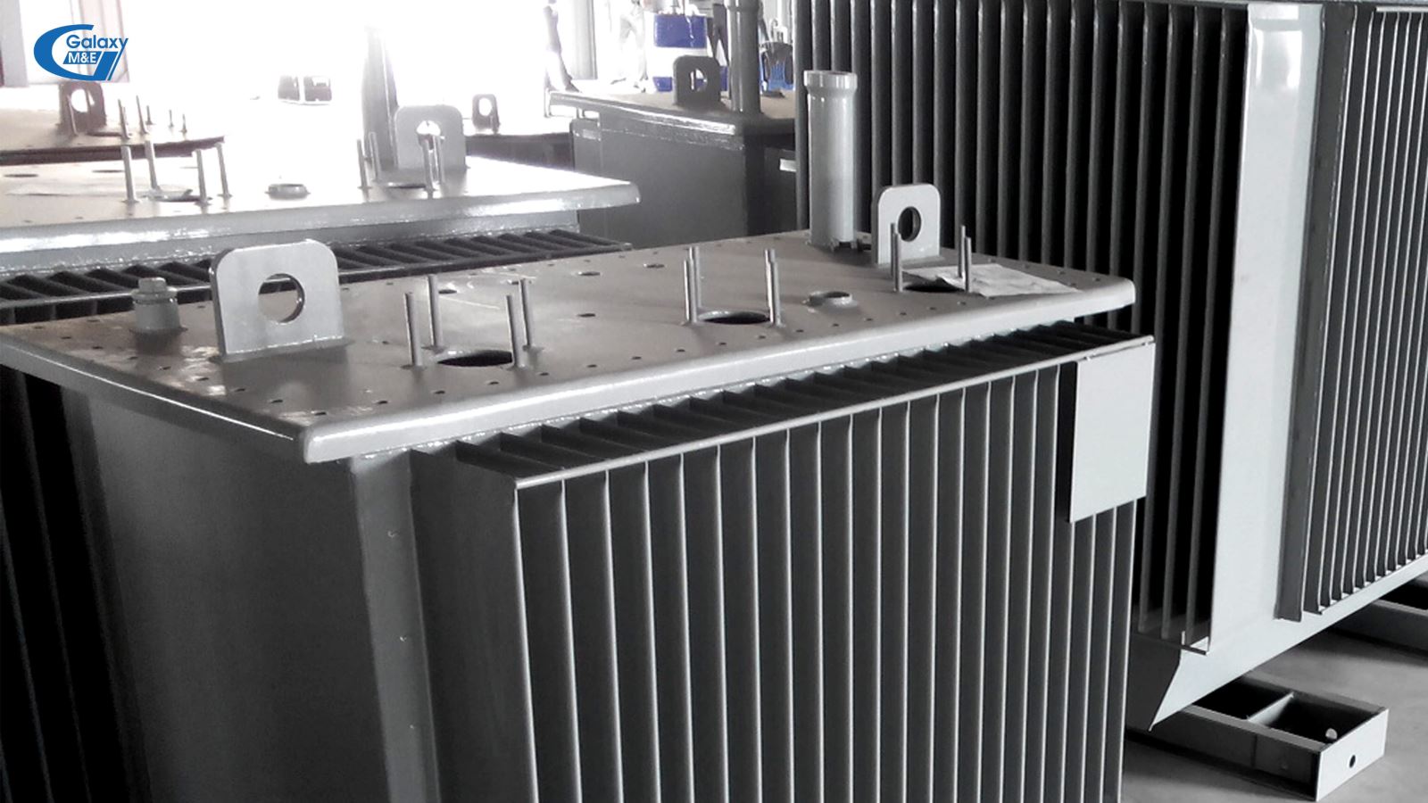
The lid is where the device comes with the 3-phase transformer.
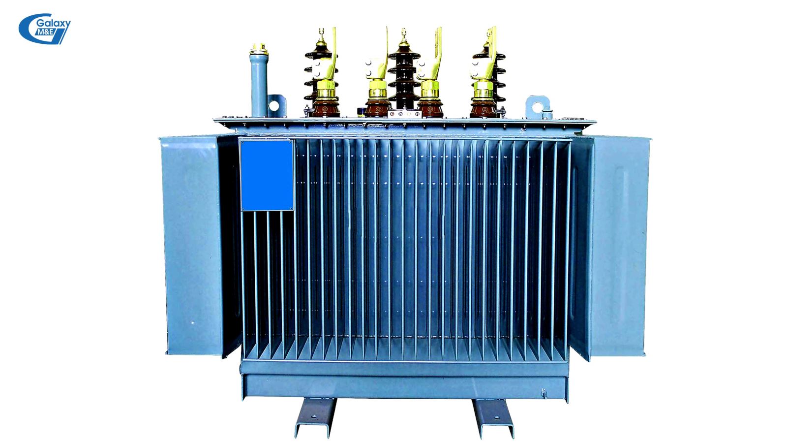
Cover part: The lid cover is used to close the box and connect to the cover with a high elastic rubber gasket. Rubber gaskets work to prevent the escape of radiator oil, and also link the lid and the barrel. On the lid of the box, a number of important details are installed, such as: High-voltage porcelain (including 3 fire-wire porcelain, 1 neutral wire) Oil expansion tank (with open transformer); Pressure Gauges; Adjustable output voltage level button; Connection terminals (cosse); Explosion-proof hose (one end is connected to the tank or oil tank, one end is covered with pressure-resistant material. If the pressure of the machine exceeds the allowed level, the cap will burst, and help release pressure, minimizing the damage harm done to the transformer).
Why is the transformer housing made of steel?
Although steel is a conductive material, it makes the transformer casing with voltages up to thousands of kV. Steel has good mechanical and chemical resistance and elasticity. Thanks to the insulating oil contained in the transformer case, the housing is not electrically powered. Also because of the insulation oil, which is also a heat sink oil, when working, heat generated from the core of the transformer will cause the oil to expand. This expansion increases the pressure in the case. Steel casing is the only material with heat resistance, elasticity and high pressure resistance. In the case of pressure and temperature of the transformer box exceeding the allowed level, the discharge tube on the lid will discharge pressure and "rescue" the transformer.
2.5. The devices are mounted on transformers
Most current 3-phase transformers are equipped with the following equipment: High voltage porcelain, low-voltage porcelain, knobs, oil level indicator, pressure reducing valve, oil release valves, gas relay, heat indicator of the oil level, temperature indicator, wire, lightning protection device, earthing, tips, desiccator.
When calculating the capacity of the transformer to be purchased/installed, it is recommended to overload the equipment by multiplying the total load capacity by a factor of 1,2 or 1,4.
3. Galaxy Electrical Contractors consulted how to choose the transformer capacity to meet the load demand
3.1. How to calculate the power of transformers
Formula for calculating transformer load: P = cosФ.M
Inside:
- P: Load capacity of equipment (kW)
- CosФ: Power factor of the power source
- M: Power of transformer (kVA)
Example of selecting transformer capacity:
A workshop with a total equipment capacity of 200 kW. Consider the power factor (cosФ) to be 0.8. So according to the above formula we have: M = P/cosФ = 200/0.8 = 250 kVA.
Conclusion: The installed transformer capacity is 250 kVA.
3.2. Notes on choosing the power level of the transformer
- Machines with a capacity of more than 1000 kVA should not be used for low voltage stations with a secondary voltage of 220/380 V and machines with a capacity of over 1800 kVA should not be used in substation which has the level of 660 V;
- It is necessary to take into account the load used in a day, a month or in a year as well as the possibility of future development;
When calculating the capacity of the transformer to be purchased/installed, it is recommended to calculate the overload of the equipment by multiplying the total load capacity by a factor of 1,2 or 1,4 (corresponding to 80% and 60%, respectively). For example, if the actual total load is 200 kVA, after multiplying by a factor of 1.4 it will result in a total load including 280 kVA overload reserve. So instead of installing a 250 kVA transformer, the investor need to install the 350 kVA transformer.
- In case of continuous power supply for loads, two or more machines should be operated alternately to ensure avoiding overload if only one unit is used continuously for a long time.
The content above describes how to classify, structure and how to choose the power of 3-phase transformers.
Structure of 3 phase transformer
In addition to the information shared, the installation of the transformer also requires a lot of specialized knowledge as well as the necessary criteria for the transformer to be connected to the grid. With the motto "Creating values," Galaxy M&E is ready to help customers consult, design, and execute all types of 1-phase, 3-phase transformers, substations, power distribution systems for the area with industries, buildings, service complexes ...
Galaxy M&E
Other news


