Let’s learn about 1-phase transformers with Galaxy Electromechanical Contractor
1-phase transformers are the most popular, currently small-capacity transformers. It is both suitable for civil needs and for industrial production. To explain why there is a common history mentioned above, Galaxy Electromechanical Contractors will introduce to you the concept, structure and operation of 1-phase transformers.
1. Concept of 1-phase transformers
A 1-phase transformer is a static type electromagnetic device that works on the principle of electromagnetic induction, converting an alternating current system at this voltage into an alternating current at a voltage different from zero.
Therefore, transformers only perform the task of transmitting or distributing energy, not transforming energy. In fact a transformer consists of two or more coils connected by a loop hook flux. If a coil is applied to an alternating voltage (primary winding) then there will be a magnetic flux generated with amplitude depending on the primary voltage and the number of primary windings. This magnetic flux will loop other coils (secondary winding) and inductors in the secondary winding with a new dynamic power, value depends on the number of secondary winding coils. With the ratio of the number of primary and secondary windings, we will have a corresponding ratio between the primary and secondary voltages.
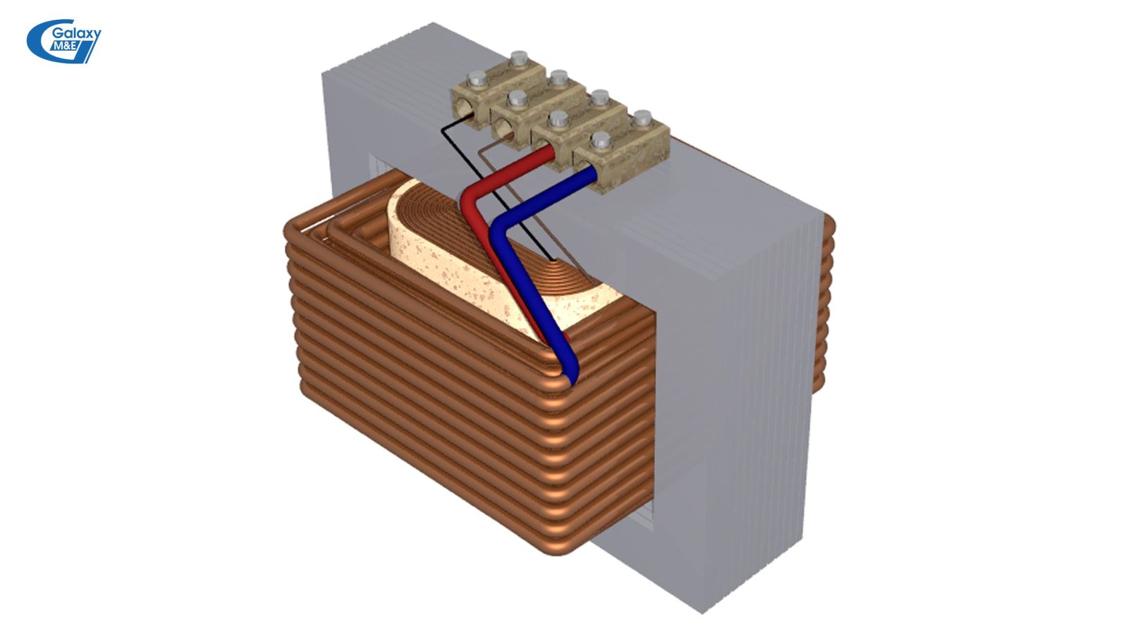
Design of 1-phase transformers.
2. Components of the transformer
Transformers are generally composed of three components: magnetic core, winding, and housing. In addition to these 3 components, the transformer has parts such as porcelain insulators, voltage gauges, temperature gauges, pressure gauges, indicator lights, etc.
2.1. Magnetic core of transformer
Magnetic core, also known as steel core, serves as a magnetic conduction circuit and also serves as a frame for winding. Typically, to reduce the losses due to eddy currents, the magnetic core is composed of electrically engineering steel sheets (silicon tole) about 0.33 mm thick. For information-based, high-frequency transformers, the magnetic core is composed of permalloy steel. According to the shape of the magnetic core, there are two types of magnetic circuits:
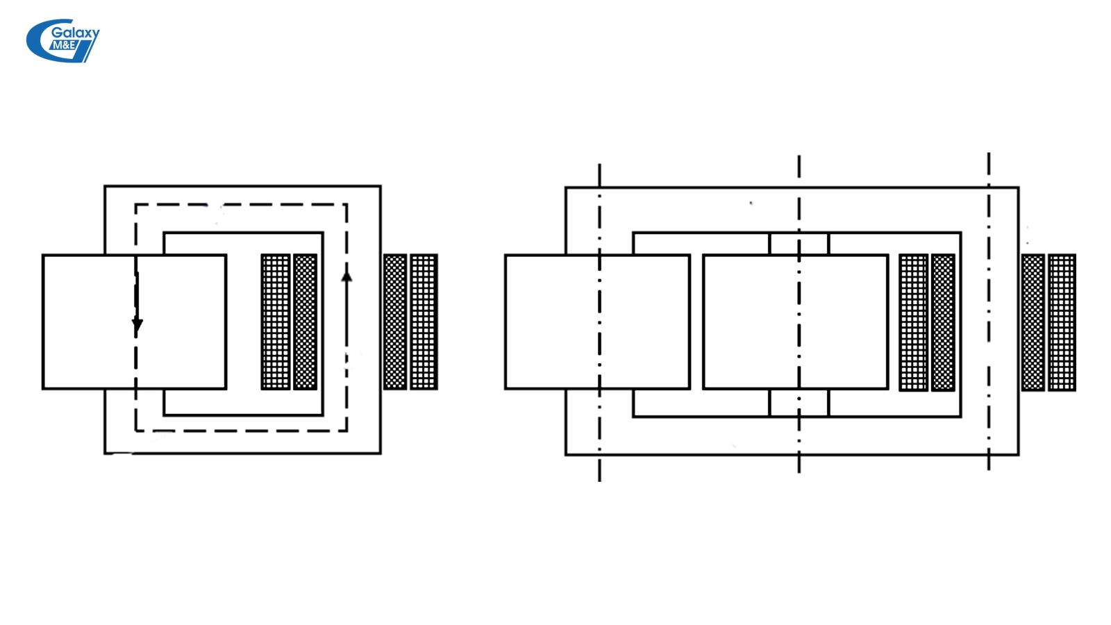
Pillar type (or core type): Winding wire surrounding steel cylinder (magnetic core). This type is commonly used for single-phase transformers.
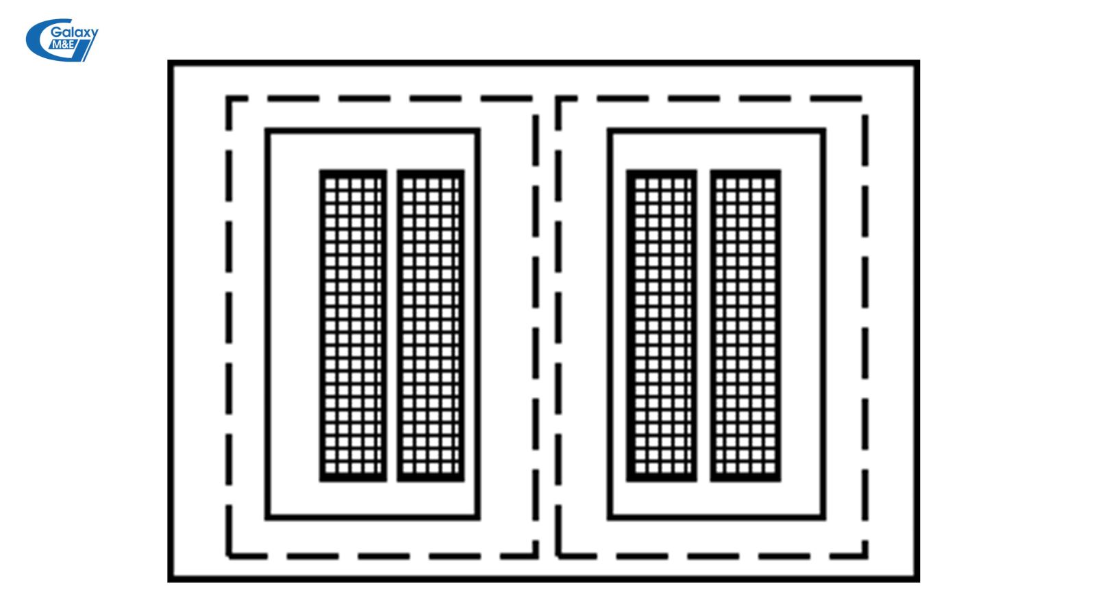
Wrapping type: Magnetic circuit is branched on both sides. This type is often used in wireless work (or applies to 3-phase transformers) ...
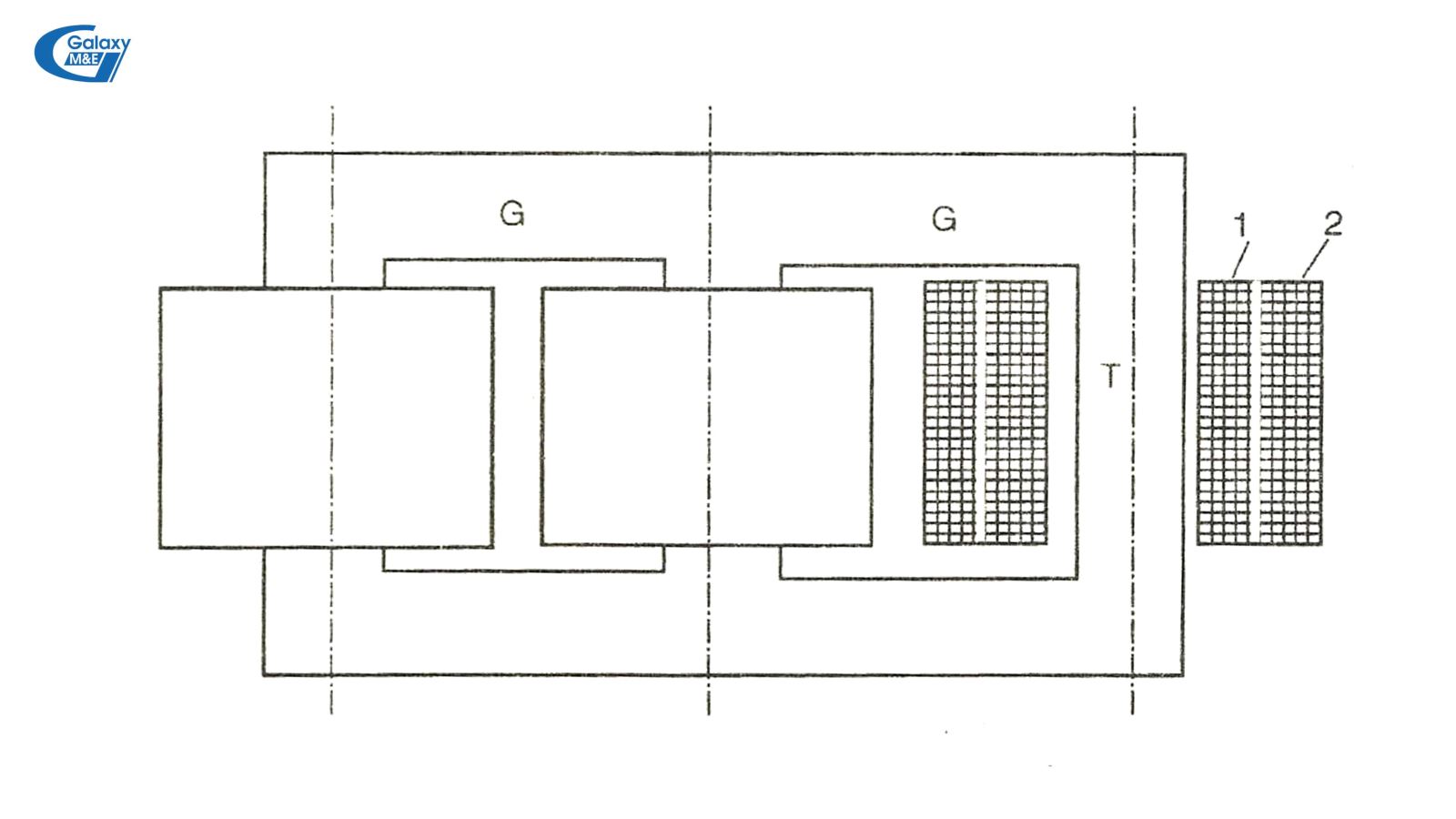
Concentric windings of transformers.
2.2. Winding wire
The winding of the transformer serves the purpose of transmitting energy. Materials for making coils are usually copper. For some low-cost transformers, instead of copper wires, to accommodate customers' affordability, manufacturers use aluminum wires.
According to the arrangement of high and low voltage cable winding, it is divided into two main types: coils and concentric winding.
Concentric winding: There is a cross-section of concentric circles. Low-voltage winding wire usually rolls inside near steel pillars (magnetic core). The high-tension winding on the outside wraps the lower pressure winding.
Alternating winding wire: The winding wheels of high and low-voltage winding wire alternately along the steel cylinder.
2.3. Transformer housing
The case consists of 2 parts and a lid.
Transformer case: Usually made of steel, shaped round / cylindrical or rectangular. For single-phase transformers for household use, due to their low capacity, the cooling is mainly based on air. In contrast to 1-phase transformers used for industrial buildings, which requires high power, to ensure the service life of the transformer, the manufacturer must increase cooling by immersing the transformer in drum. Thanks to convection in the oil, heat is transferred from the components inside the transformer to oil and then from the oil through the radiator housing to the surrounding environment. Depending on the transformer capacity, the shape of the oil tank is different. For single-phase transformers with a capacity of 30 kVA or under, a smooth and flat oil tank.
Barrel cover: Used to fill the oil tank (for oil cooler). On the lid, there are other details such as: Porcelain insulating the output of low and high voltage winding. In addition, the voltage and pressure gauge is provided inside the case.
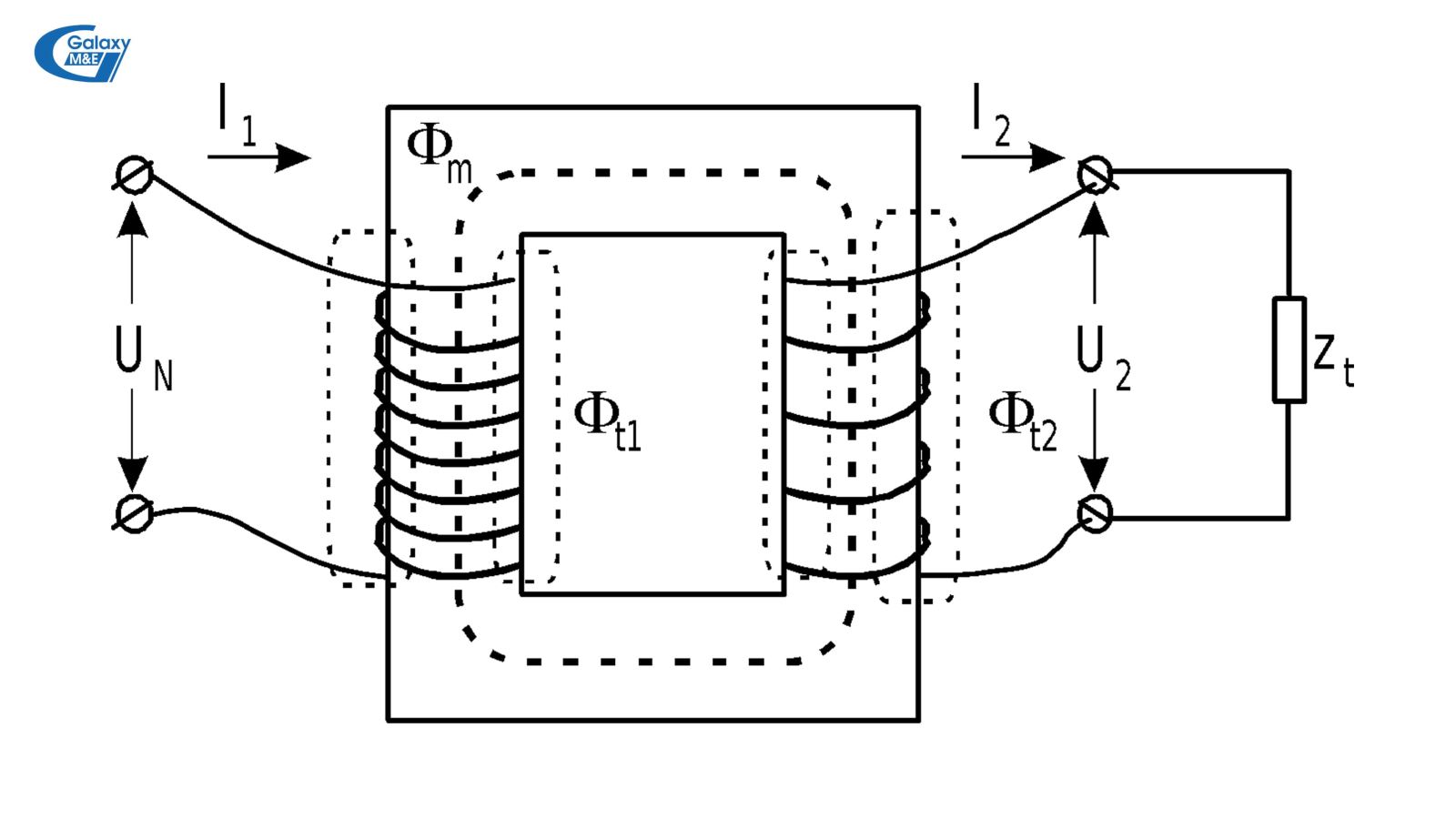
Principle of operation of the transformer.
3. Operation principle of the transformer
The transformer operates based on the concept of electromagnetic induction. For increased efficiency, the magnetic circuit is composed of a good conductive material (silicon tole).
Winding 1 has N1 turns and winding 2 has N2 turns wound on steel core 3. When applying an AC voltage U1 to winding 1 (primary winding), there is I1 current running in winding 1. The steel core will generate magnetic flux Ф hook with both coils 1 and 2, inducing the electromotive force e1 and e2. Winding wire 2 with electric force e2 will generate current I2, giving the load with alternating voltage U2. Thus, the energy of alternating current has been transferred from winding 1 to coil 2.
* If the applied AC voltage is a Sin function, the flux generated by it is also a Sin function.
* Ф = Фmsinωt. Therefore, according to the law of electromagnetic induction, the induced electromotive force in coils 1 and 2 will be:
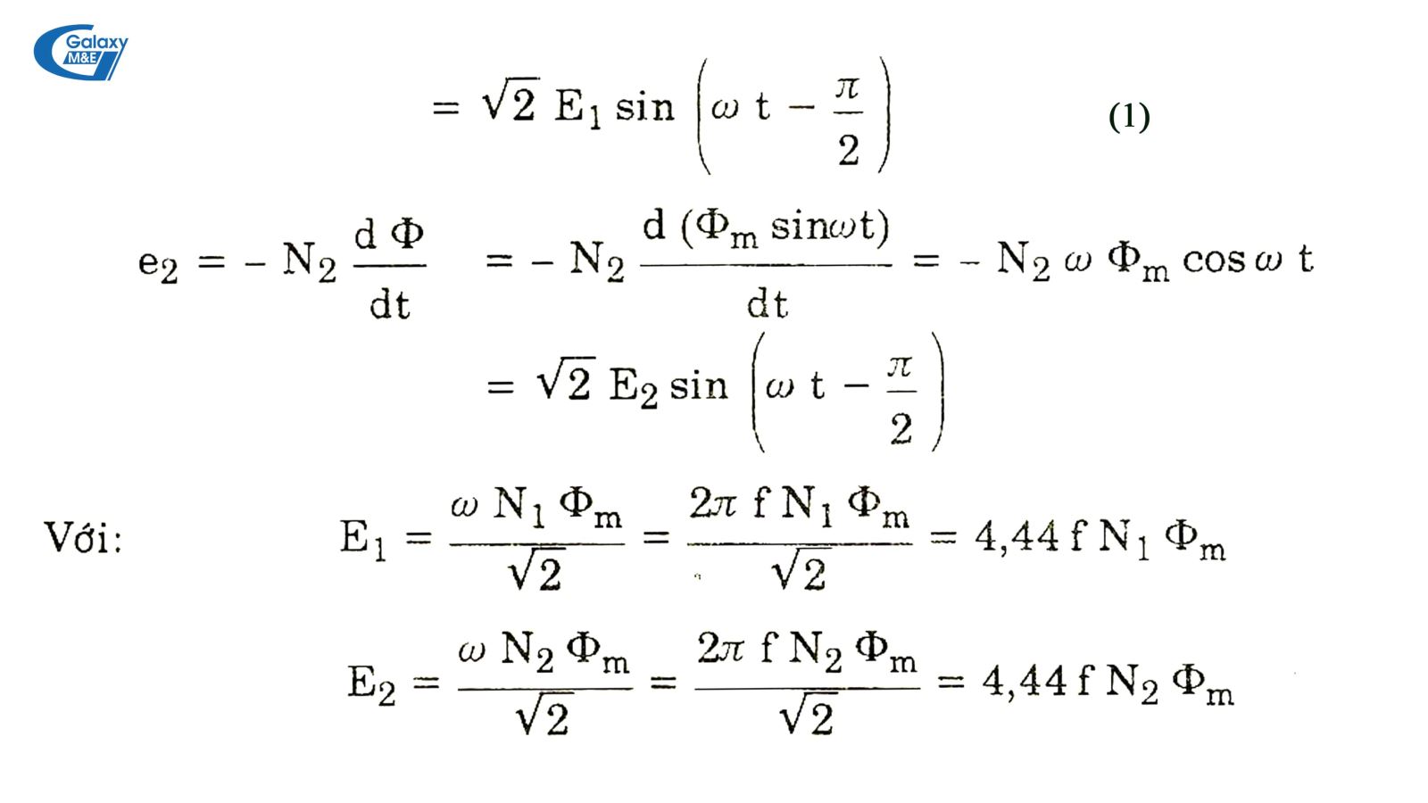
The formula for calculating the electromotive force is based on the law of electromagnetic induction.
With E1 and E2, respectively, are the effective values for the electromotive force e1 and e2. Equations (1) show that the induced electromotive force in the coil is always slow to phase with the magnetic flux producing it at an angle of π / 2.
The conversion ratio of the transformer is defined as follows: k = E1/E2 = N1/N2. If the voltage drop on the windings is omitted, U1 ≠ E1 and U2 ≠ E2 can be considered, so k is considered as the ratio of transformer between winding 1 and winding 2 with k = E1/U2 = U1/E2.
4. Rated quantities of 1-phase transformers
Usually the rated quantities of a transformer are specified by the manufacturer, which gives the technical features of a single-phase transformer.
- Rated power: This is the total power at the secondary output of a single-phase transformer. The unit of calculation is VA or kVA;
- Rated primary voltage: It is the permissible voltage applied to the transformer primary winding, the unit is V - kV;
- Rated secondary voltage: It is the measured voltage at the secondary output at no load, the unit is V - kV;
- Primary and secondary rated current: It is the current allowed to run through the primary and secondary windings corresponding to the machine's rated power and voltage. The unit of calculation is A or kA.
5. Use a 1-phase transformer as noted by the M&E contractor
When using a 1-phase transformer, the user should note:
- The input voltage shall not exceed the rated voltage of the transformer;
- Do not let the transformer work beyond its rated capacity;
- Put the transformer in a dry, cool and dust-free place. In particular, do not expose to damp places which can lead to damage to the transformer and may cause fatal accidents;
- Absolutely follow the instructions given by the manufacturer;
- If the use process causes a breakdown, a voltage drop or a wall is leaking, immediately disconnect the power source and notify the transformer supplier or the manufacturing unit. In case that the supplier cannot be contacted, the user should contact mechanical and electrical engineers for advice and solutions.
- Absolutely not arbitrarily repairing or changing the structure of a transformer without specialized mechanics and transformers;
Above is the basic information about 1 phase transformer. The provision of this information is not outside the purpose of Galaxy M&E that wishes to contribute to customers and the whole society to use electricity more safely on the basis of fully understanding about mechanical and electrical. In addition to the 1-phase transformer - the most popular and closest to everyday life, in the actual transmission and distribution of electricity, the 3-phase transformers and substation are more complex in structure. The structure of a 3-phase transformer will be sent to readers in the following articles by the Mechanical - Electrical Galaxy.
Galaxy M&E
Other news


